
General navigation and use
 The nx-interface a touch screen display. The navigation from one page to another is done by pointing/clicking on an element.
The main icons used for navigation are:

|
Access to main menu. This icon is on every screen and click on it to come back to the top level and navigate quickly |

|
Access to settings (level3). There are prepared graphical screens for setting and an access to the whole list of settings with the + symbol from there in EXPERT mode. |

|
Access to detailed lists of information (from info screen) or list of settings (from settings screen). The + is accessible only in EXPERT MODE for list access. |

|
ON/OFF of all the functions of the inverter. A confirmation is asked |

|
Back on the previous screen in the menu hierarchy |
|
|
Enable or mute the beeping of the remote and the inverters. |

|
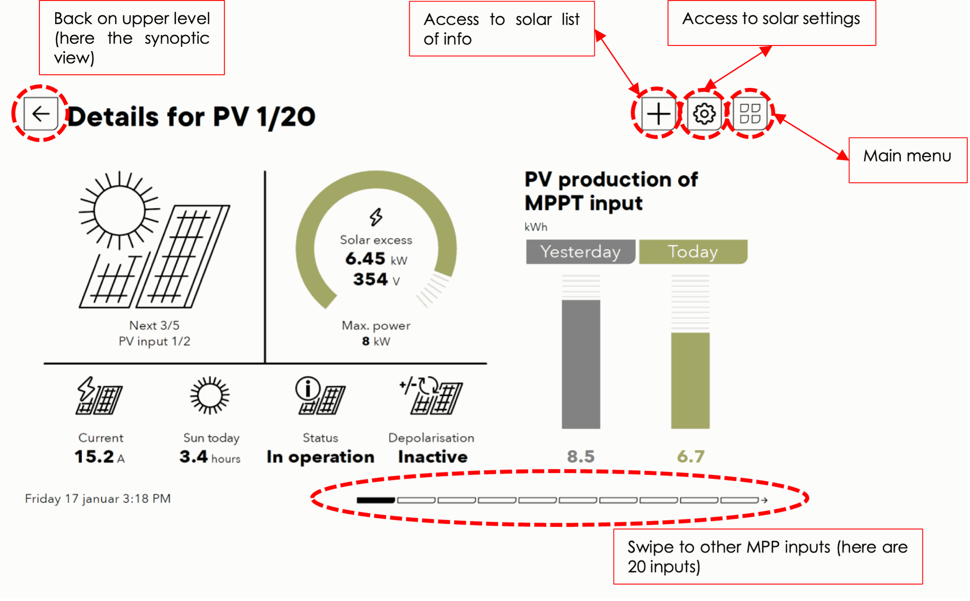
Page indicator: you can swipe left/right to move to different pages of the same level. For example, when there are many solar chargers in the system, you can navigate from one to another. |

Example for the information screen of solar:
Screens map
The navigation on the nx-interface is organized as given by the picture below. A locked screen appears after some time of inactivity on the nx-interface. It is unlocked with a slide move or with a code. From the locked screen you go back to the last screen that was displayed before entering sleep mode.
The main menu is always accessible form any screens with the icon: available on each screen.
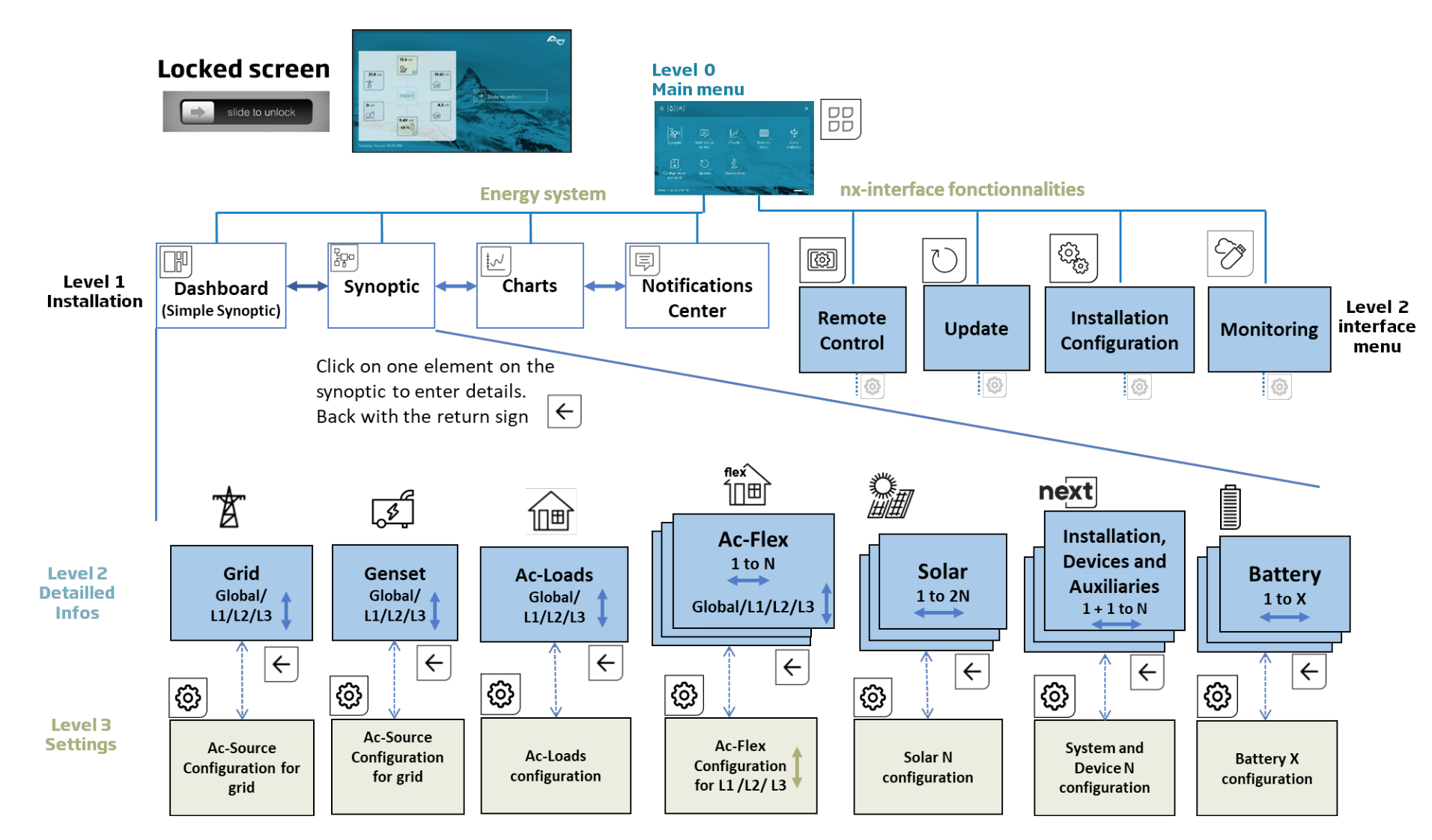
The nx-interface screen is organized with screen levels
- LEVEL1: general view of the state of the energy system, the instant values, the history, and the message log.
- LEVEL2: Information about each component (AC-source, Battery, solar,...)
-
- Many detailed information that can be obtained from the next3 about the inverters operation. For example the AC-reactive power of the phase 2 on the AC-source connection can be seen by going on the AC-source from the main synoptic.
- LEVEL3: Programming: the settings about each component can be seen or modified.
Note: when on a configuration screen (Level 3), the settings are for a unique component. Per exemple there are two solar mppt entries on one next, the settings are accessed individually.
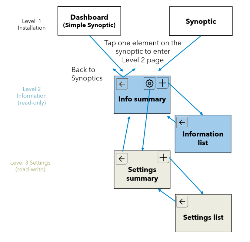
For convenience and simplicity, not all information can fit on one screen. From the level 2, the “plus” button allows to access a list of detailed information.
From the level 3, the “plus” button allows to access a list of detailed settings.
The “plus” of level 2 and 3 is accessible at expert level only. The unique reference identification number are used in communication and to clearly identify the information/settings.
Navigation from the synoptics to the detailed information and settings of parameters:
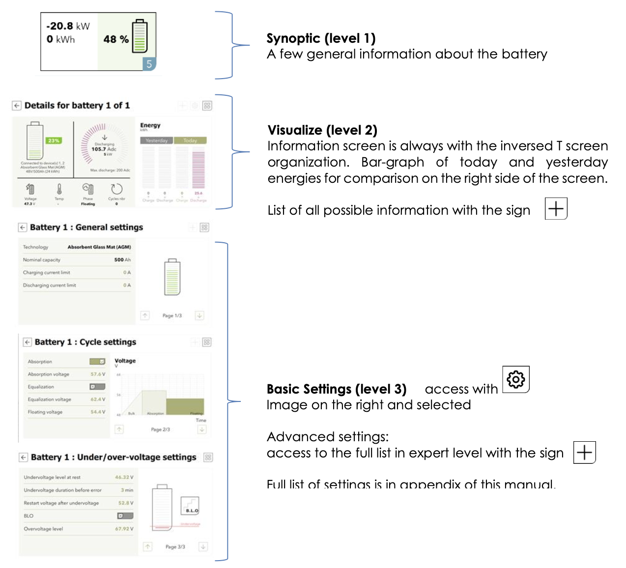
Example with the battery
See the following chapter to have details about each component of the energy system (the solar, the AC-source, the AC-Flex, the battery, ...)
Embedded documentation
The nx-interface has an embedded documentation about all information (level 2) and settings (level 3) available.
- Access to documentation about one setting/information by clicking on its name
- Change the settings by clicking on its value

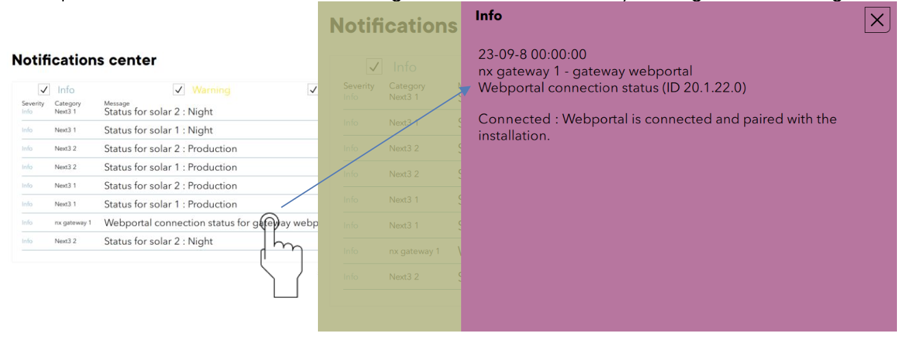
The explanations about the received messages are also embedded by clicking on one message.
The full list of information and settings with their default values, units, ranges, and explanations can be found in the Object Model description. Each parameter/setting/information has its own unique identification number starting with the prefix ID. The same documentation is embedded in the nx- interface.
Accessibility
User accessibility: can be changed in the nx-interface menu with user levels. The levels are:
- View Only: the user has access to levels 1 and 2 of the screens (dashboard, synoptic, graph, messages, view of components information). The configuration icon
is not accessible and the user cannot change anything in the configuration of the system. Code is 00000.
- Basic: the user has accessed to the level 2 and 3 It is possible to modify the configuration of the next without the full list of settings (the full list icon
is not accessible). The important settings for the standard operation of the next system are available on the prepared screens of level 3. Code is 815566.
- Expert: the user has accessed to all information and settings. Access is restricted for end-user as the grid code settings must be chosen by the qualified installer at commissioning and modifications are not allowed. The expert code is delivered only to qualified installers.
On the first commissioning the nx-interface is set to Expert to allows the use of the wizard process and then automatically set down to View Only.
The modification of the user level is done with codes in the nx-interface, in the remote control screen and then on the configuration menu (  →
→ )
)
The codes are:
View Only 000000
Basic 815566
Expert For professionals only

Blocking access with customized code
The slider of the locked screen can be replaced by a code to unlock. This prevents the modification of the system by unwanted people.

The activation of this code is done in the remote control screen and then on the configuration menu
( → ). It is available for experts only. The unlock code can be freely chosen.

Displaying the state of the energy system
The actual and historical state of the energy system can be seen on the screens of Level 1 of the energy system.

The status of the energy system is seen with two screens the simplified dashboard of the synoptic.
Simple dashboard
 Power fluxes and state of the battery can be seen. In one blink you know what your production is, consumption and general state of the system. All powers are the sum of all devices and all phases. The same general overview is on the “locked screen”.


Synoptic
 The detailed synoptic gives access to the information and the programming of the various components (click on it):
- AC-Source: the AC-grid or a genset. There is only one AC-source connection in a system.
- AC-Loads: the consumers: there is only
- AC-Flex: A special entry that can be configured as
-
- A second source, there is only one second source connection in a system. The AC- source has priority of connection over the AC-flex as second source.
- A controllable load, in that case there are as many AC-Flex as loads than the number of nx device in the system.
- Battery: there can be many in a system.
- Solar: connect the two PV strings.
- Device and I/O (AUX contacts, Remote Entries, COMM ports, ...): on every nx device of a system.
From the dashboard or the synoptic, the details of each component are accessed by clicking on it. See the general screens map in previous chapter for an overview of the navigation.

 Note that the AC-source as genset and the AC-flex as genset are missing on the figure above as we cannot display all the different configurations on the same screen.
An important alert on one of the components can be seen with a change of color. It is associated with a warning or error and with a message explaining what happens.
Detailed maps of levels 2 (information) and 3 (configuration) for the energy system:

Simple chart
 The energies of yesterday (00:00 to 23:59)and today (00:00 to now) are shown in a bar graph.

Power and battery time series will appear with future updates.
Messages
 List of messages/events that happened to the system.
The errors and warnings are in red when they appear and in green when they are cleared. It is possible to filter the message in function of their severity:
- Information: an normal event happened in the system and is logged
- Warning: something abnormal happens and the next3 operation can be restricted but the device is not stopped.
- Error: an event that stops the operation of one of the component of the next3 or the whole next3 happened.

Functionalities nx interface
The nx-control has 4 dedicated menus for settings and actions specific to the interface:
- Remote control: manage the nx-interface itself (user access, language, brightness of the screen, ...)
- Updates: update of the whole system is done with the nx-interface with by copying the new firmware on the usb key.
- Configuration of the installation: start a new configuration wizard here.
- Monitoring and internet: set connection to the Studer webportal and manage the datalog on the usb-key. The Modbus M2M communication for monitoring by external SCADA system is also managed here.

Remote control
 This menu is for the nx-interface itself (Language, user level, brightness of the screen, ...). The physical connections are also shown, with the positions of the bus terminations on the nx-interface: very useful to find them as they are a little bit hidden under the nx-interface.

This menu give access to the user levels. The codes are:
- View Only: 000000
- Basic : 815566
- Expert : For professionals only
The connection view helps to locate the connectors on the side (usb) and under the nx-interface:

Date and time
The next3 features a real time clock that allows among others to have a correct date and hour for the datalogging records. This clock must be set using the remote control nx-interface. Thanks to an internal battery, this setting is retained even when the equipment is disconnected from its voltage source (battery or PV).
If the nx-interface is connected to the internet, the date and time is automatically updated if you accepted it at the initialisation (during the wizard).
USB memory stick management
Hot Plug of USB memory is possible. Always remove the USB using the EJECT button on the nx-interface. The eject button is available in different menu and has the same effect.


The USB-stick is also used for
- Datalogging backup
-
- Procedure: see the monitoring section
- Update of the systems.
-
- Procedure: see the update section
- Manual savings of the configuration and files (to come)
-
- Procedure: see the configuration section
With the code version 1.0.0 of the nx-interface, one USB key per system is managed. If a USB is already plugged in and you want to plug another key, remove it first.
Update
 This part describes the update of the next system (inverters, nx interface and accessories) using the nx-interface.
In the update screen, you can choose which source will the update come from:
- USB key: Download the latest software version from our website: https://www.studer- innotec.com/en/downloads/ in the support and download section, unzip and copy the whole folder called “next3-system-update” at the root of the key. The usb-key must not be removed until the end of the updating process. If for some reason the updating process is interrupted, restart it to let the process finish.
- Internet: The update via internet is available from version 1.2.x.x. For older version you’ll need to perform the update with the USB key first. The USB key is mandatory even for the internet update, as the files are copied on the USB key.

Press “search USB” and the nx-interface will check the USB key and the update server.

After the check, the screen informs you if an update is available. The current (black) and the available update (green) can be seen on the right side. Information are displayed in case of incompatibility.


Once the update ready, you are informed of the available versions, and you can start the update of the system with the “Start Update” button.
The update is performed in many steps: first the nx-interface is updated and then you must press again on the “start update” button for the next2 devices.
The updating process can take between 3 and 15 minutes. NEVER disconnect the battery during an update. During this process, the installation is stopped, and the AC power supply is interrupted. Choose the proper moment to process an update.
When multiple elements are connected to the nx-interface I and to the next3 by the communication bus, it is possible that the software versions are not compatible. It is highly recommended to update the software of all components in the system to guarantee all functionalities.
Therefore, before starting the setup of the device, download the latest software version from our website: www.studer-innotec.com on an USB key. Follow the instructions in this manual for a successful installation.
Installation configuration
 In those pages you can reconfigure the next energy system from the start with the wizard, and also save and export configurations for your backup or to replicate it on other installations. The configuration pages are available at expert level only.
A summary of the system is available on the main screen and a list of all present devices of the system is situated on the left. The “Config details” button give access to numerous detailed technical information (list of all hardware used, list of all FID, ...) that may be necessary for support purposes.
For a factory setting reset, you must run the wizard again. It will reset all the values with the factory values according to your configuration.
Configuration Wizard
The standard configuration of the next3 energy system is done with a configuration wizard. It is possible to modify single settings individually later the pages dedicated to each topic of the converter. On the first commissioning of the next3, the wizard will be automatically started, and all steps must be followed. To restart with factory settings, you must run the wizard again on an installation.
All the settings previously set are forgotten when running a new wizard.
The wizard is automatically launched on the first commissioning of the next3. At the end of the wizard process, the nx-interface is set back to the basic level. This is necessary to avoid the change of critical settings later by end customer (grid codes).
To access the wizard, you need the expert level.
In the first steps of the process, the wizard asks the language that will be used for the configuration and later.

Then questions are given to configure the energy system itself. Comments are done about the steps in the corresponding sections of this manual, in the chapter “configuration and operation of the next”.
If you stopped in the middle of the process or the installation has changed, there will be an error message:

Finish or restart the wizard process in that case.
Back-up and restoration of the configuration (TO COME)
We invite the installer to perform a saving of its configuration at the end of the commissioning and keep it to restore the configuration (in case of device exchange, or unwanted modifications by the customer).
The backup is done with files copied on the on the usb stick. Keep the whole folder “nx-backup”

Note: if the configuration of the system is different (different types of devices, not the same number of devices, ...), the restauration of a configuration is not possible and config files will be refused. In that case you must start a new configuration with the wizard.
Monitoring & datalogging
 See the monitoring section
Configuration
Many settings can be changed to adapt the configuration of the next3 to the environment/system.
The nx-interface operates as a terminal and is not mandatory in a system. It can be plugged to the system and removed. When an inverter/converter setting is modified using the remote control (nx-interface), it is sent to the next3 and stored in the device permanently. If the nx-interface is removed from the system, this parameter continues to be used by the next3 with this modified value. If the next3 is de-energized and then energized again, the settings can be retrieved from the non-volatile memory. This allows for example to pre-program a next3 at the workshop and to supply it to a customer, ready for his specific application.
The settings are secured against inadvertent or unauthorized change by the user level. The change of the user level is protected by password and must not be done by unauthorized personnel.
The next3 cannot operate until a regional setting (grid code) has been selected during the configuration wizard. The configuration wizard shall be done by an authorized person. If the initial configuration is not finished, the inverter does not start and the ! red light of the front panel blinks permanently. That means without a proper selection/activation of the regional configuration the inverter doesn’t start and doesn’t connect to the grid.
Configuration wizard
At the first commissioning of the next3 a configuration assistant called the “Configuration Wizard” will be automatically started on the nx-interface. With a set of questions, the user is invited to configure the next3. Very specific settings can always be accessed later in each component’s menu.
The process with the wizard is mandatory for new installations and with multi-unit systems.
It is also possible to run it later by going to the nx-interface menu “Installation Configuration” (available at Expert level).
Path:  launch →
It will reset all the settings with the factory values according to your configuration/answers to questions. Old configurations are completely erased with a wizard process.
During the wizard process, the installation is stopped, and the AC power supply is stopped. Choose the proper moment to perform a configuration wizard.
The use of wizard is mandatory in case of multi-unit systems. That means an nx-interface is mandatory for the commissioning of multi-unit systems.
After a few questions for the remote control / nx-interface configuration (time, date, …), a scan of the devices present on the communication bus is performed:

Check that all the elements you want in the system are connected. LEDs of front pannel of the next are all blinking during this process. If not, that means the communication cannot be established. Check the communication cabling (presence of cable and termination switch) and that all the units are powered on (energized from a battery).
On a can bus, impedances are connected at the two ends of the communication line to “terminate” the line. Without those terminations as pull down resistors, the communication doesn’t work at all. If the system doesn’t see any nx3 in the system, check the nx bus termination switch on each device. It has to be on ‘T’ at the end of the line (when there is only one communication cable to the device) and on ‘O’ in between (when there are 2 communication cables to the device).
In the next step, the system checks that 2 impdances are activated:
The termination switch is at the bottom of the next3: set T for terminated and O for open

And on the nx interface:

Once all devices are connected and detected by the nx-interface you can go forward. The country and time zone is set in the point 3: General:

The country selection doesn’t influence the grid code choice that is set with the AC configuration (to cope with different local rules in the same country):
Next step contains the question about the AC (sources and loads)
- First question is to know if there is a grid or not connected to AC-source. The grid is always assigned to the AC-source due to the double security relays.
-
- If YES the properties of the grid connection are asked:
-
- introduction amps (circuit breaker size)?
- Is grid feeding allowed or not?
- Which grid code must be used? the grid code must be set according to the DSO requirements.
- Those values cannot be changed later except with a complete reset of the system.
- In a multi-system, you must indicate which device is physically connected to the grid as there is only one device/transfer used per system. The selected device is blinking for a visual check.
- Don't connect a genset on the AC-Source programmed for grid as the configuration is very different. If you have a genset, simply say no to this first question and the genset question in on the next page.


Use of the proper grid code is a legal requirement; you must be sure (as installer) to respect local regulation. Associated with a general grid code (like the EN-50549), there can be special local settings. In case of doubt contact your local DSO (Distribution System Operator) before selecting the grid code in the country list:
- Then comes the genset question to know if there’s one in the system:
-
- If there is a genset, the user must indicate to which connection it comes. A genset can be connected to the AC-source or the AC-flex connection.
-
- In a single device system, if the AC-source connection is used by the grid, only the AC-flex is left. If there is no grid (OFFGRID), the user has the choice to use AC-source or AC-flex. It makes more sense to use AC-source as it leaves the AC-flex for loads.
- In multi-units system, if there is a genset, the connection could be done on any of the free AC-source or AC-flex and this must be indicated. It is better to use an AC-source connection if possible and let the AC-flex free for loads.
- The maximal power taken from the genset will be the lowest of the power given and the current limit.
-
- When a genset is three-phase the power is divided by 3, and the power limited by the current of the circuit breaker expects a 230Vac.
- All AC-flex that are not explicitly given as AC inputs will be configured as loads, even if there is no specific question asking for it.

Per example without genset all AC-Flex are used for flex loads:

And last point for the AC is the question for the AC-coupling. If the grid inverter is connected to the AC-Flex connection, you should make the proper settings for the AC-flex relays. See the AC-coupling section for details.
- Then come the battery questions with, first, the choice if the battery is communicating or not
- If the battery has a communication BMS (typically for lithium battery), you’ll have to choose the manufacturer in the list for the next3 to use the proper communication protocol. Verify that the manufacturer is in the compatible list.
If it is not the case, contact your provider to avoid any mistake which can lead on problems in your installation.
Then enter the capacity of the battery. Very often the lithium battery has a capacity given in kWh and not in Ah. Convert with the following formula: Capacity in kWh *1000/Battery voltage =Capacity in Ah
For example, a 10kWh at 50V battery has 200Ah.
- At the end is the second important question for the energy strategy:

In the battery cycling is wanted (charge-discharge frequently), the SOC for backup will be set to 20% (for lithium and 50% for lead acid). If not, it will be set to 100%.
is done. If not (simple lead acid batteries for example), then you must enter the type and the capacity in Ah.
The capacity is asked in Ah, if this is not given directly by the manufacturer this is obtained with the formula: kWh / voltage x 1000
The non-communicating batteries are generally lead batteries. Choose the appropriate type in the proposed list. In case of doubt select AGM batteries: it has the less risky levels (lowest voltages) for any types of batteries, even if the charging would not be optimal for other cases:
|
Floating voltage |
Absorption voltage/period |
Equalization
|
Charge current |
|
|
Flooded Lead Acid (without equalization) |
54.4V |
57.6V / 2h |
No |
C/5 |
|
Flooded Lead Acid (with periodic equalization) |
54.4V |
57.6V / 2h |
63.2 V during 30min- every 30 days |
C/5 |
|
GEL |
55.2V |
56.8 / 2h |
No |
C/10 |
|
AGM |
53.6V |
57.2V / 2h |
No |
C/3 |
There is no reduced floating phase or periodic absorption phase for any of those choices by default.
If you are not satisfied with one of those pre-sets, you can go to the battery menu later and adjust the levels as you want.
The battery capacity is generally given in Ah for lead batterie and other special types. For a battery bank composed of many cells, the arrangement gives the total capacity. To calculate the capacity, only one cell capacity must be considered in a series and not the sum. If the battery bank is composed of several series/strings in parallel, the total capacity is the sum of the capacities in parallel.
Per example a with 24 units of a 200Ah/2V cell in series, the total battery bank is 200Ah 48V. With 72 cells arranged in 3 strings of 24 units, the bank is 600Ah 48V.
To determine the charging current, the most frequently used value is of one fifth of the battery capacity. Ex. for 500Ah: 500/5 = 100A. See manufacturer indication for details.
-
In case of multi-unit system, the number batteries is asked first

And then each battery must be associated with its next3 correctly (with the blinking of LEDs - If your next3 is connected to internet and to the Studer web portal (www.portal.studer-innotec.com) you must make the pairing with your account. This is done with the unique number called GUID. Copy exactly this number on both side for pairing. A GUID can be generated by the nx-interface, or by the web portal.

This GUID must be copied on the webportal in the GUID field when creating a new installation:
The remote monitoring can be restricted to “view only” access. This option is check by default (security by default). Uncheck it if you want to be able to change remotely setting after the commissioning. This can be very useful for the installer to avoid to travel physically to the site for some adjustments. The communication infrastructure of Studer-Innotec is up to date and secure but some customers want this restrict this functionality and option is available.
Finally, the terms and conditions of the webportal must be accepted for privacy reasons. The load curves are personal data and the end user must give its agreement that the data are sent to Studer-Innotec. Else the next3 will work normally but will not connect to the portal.
identification and serial number is displayed).
For a single battery in a system with multiple next3, it is necessary to say which next3 is physically connected with the CAN communication cable as only one device communicates to the BMS.
- Final check: a summary of the installation is given and the configuration process is finished. Press “Start using the system!”


After the first configuration with the wizard, the next3 is ready to be used.
AC Source
The next3 is a hybrid inverter charger, that can work in a stand-alone (offgrid) mode or connected to an external AC source, being a grid or a generator.
The next3 has a connection named “AC-Source” where the main AC source is connected: the grid or a generator.
This input:
- is limited to 80Aac and is designed for 3 phases system 400Vac with neutral.
- has a high security level with double security relays for disconnection according to VDE-AR-N 4105, EN 50549-1, IEC/EN 62109-1 and other standards. In case of connection to a distribution grid, always connect the grid to AC-Source. The proper opening of the relay is checked with measurements.
- is unique in a system. Only one AC-Source is physically connected in a system even with multiple next3 devices.

- The maximum accepted voltages at the input are by default (for grid connection, VDE values):
-
- 125% of nominal voltage for 10ms (for fault ride thought: 230*1.25=287.5V
- 120% for 5 second: 230*1.2=276V
- 115% for 60sec means: 230*1.15=264V
AC Source information
The detailed information about the grid is available by clicking on the AC-source picture of the synoptic screen (see screens map for an overview of navigation).

There are dedicated screens for AC-source information (see the screen map). On the L1-L2-L3 screen, the sum of all phases is displayed as well as the composed voltage (phase to phase).
The scale for the max power is given with the current given by the maximal power introduced during the wizard process.

The detailed information about all voltages and currents for each phase is available with a click on the phase number:

Similar view is given if a genset was configured for the AC-source: 

The full list of available information is accessible with the ‘+’ and is described in the appendix. Unique identification numbers are used to clearly identify each information value.

AC-source settings for grid
The wizard is mandatory for a proper setting of AC-source as many points are configured during commissioning and cannot be changed later. Carefully read the questions to avoid mistakes in your answers.
One example is the grid code setting that must be set according to the DSO requirement by the qualified installer and cannot be changed later by the end-user. The end-user has no access to this parameter as it is protected by the EXPERT code.
At BASIC level only the following settings are accessible:

Concerning the grid code, the anti-islanding function implemented is based on the power variation method (called also “vector shift” method in EN and VDE). The reactive power management with functions Q fix, Q(U), cosφ fix and cosφ(P) can be configured, if necessary, after the wizard.
For more information about how to configure the reactive power management please go to the advance grid/dso management section.
AC-source settings for genset
The wizard is mandatory for a proper setting of AC-source as many points are configured during commissioning and cannot be changed later. Carefully read the questions to avoid mistakes in your answers.
If the source is a genset, the available settings are given on 2 screens:

The rated current taken on each phase can be changed on the fly when the generator is running to adapt to its real ability.
The Observation Time can be understood as a delay for the genset to warmup.
The tolerances on the voltage fluctuations of the genset can be adapted:

Solar PV
Two strings of solar photovoltaic modules can be connected to the next3 with two independent MPPTs. Indications about the connection and dimensioning of the PV array is given in the “Wiring chapter 4.4. Be careful to meet the electrical specifications and never exceed the maximal values to avoid damaging the unit.
This section explains the operation of the solar MPPTs. All information and settings are accessible via the nx-interface
General information
The next3 is a renewable energy friendly converter and always try to optimize the solar part in the system. For a standard user, there is nothing/little to modify for the solar converter: as soon as there is solar energy, the next tries to use it first.
All the settings about this general behaviour are set during the “Wizard settings” process. During operation, all the limits and constraints are automatically managed by the NX3. Power production and storage is optimally dispatched in the system thanks to the OPFD technology (Optimal Power Flow Dispatcher®).
The solar grid feeding can be authorized or disabled depending on the AC Source type: grid or genset. There are dedicated screens in the AC-source settings on the wizard where you chose if grid feeding is allowed or not.
The PV production depends on the irradiance on the PV modules of course, but also on other constraints in the system:
- If it is an off-grid system, the solar energy will directly supply the loads and charge the batteries. However, if the battery is full and the loads are small, the solar production will be reduced. That is because the energy can go nowhere, so the excess is lost to avoid overcharging the battery.
- The charging limits are given by the battery settings (see Battery section 7.5). The next3 smart inverter can be connected to lithium batteries with communicating BMS on CAN bus (see compatible list in chapter 4.2.7). In that case the manufacturer BMS decides the voltage levels and currents that are optimal for the battery. There are dedicated screens for the battery settings on the wizard.
- During grid feeding, the max power will be limited according to the AC-source breaker amps configured during the wizard.
- The solar production can be limited according to the grid code that requires grid support function, for example the production reduction in function of the grid frequency.
To optimize the solar power use, for example with dump load connection, you can use the AC-Flex connection or the auxiliary contacts. See the section “AC-Flex” (chapter 7.7) and Aux-contacts” (chapter 0) to adjust their settings for solar maximization.
The proper insulation of the PV+ and PV- is checked at every start-up. An error will be shown on the screen if there is ground fault and the inverter doesn’t work for security reasons.
Solar information
The solar MPPT electrical information can be seen on the remote control nx-interface, on the web portal and the APP (if connected) or accessed through communication (MODBUS TCP or RTU).
On the nx-interface, the synoptic info screen shows the power fluxes in the system in kW. This view shows the solar power sum of all devices (all solar chargers, all nexts, …) in the communication bus.
The detailed information about all voltages and currents for each MPP entry is available by clicking on the solar picture of the synoptic screen (see screens map for an overview of navigation).

The detailed screen shows the information of only one MPPT channel at a time. Swipe right or left to access the information from the other MPPTs.

Note: one nx3 device has two (2) PV MPPT inputs and there are therefore two screens. In case of multi-inverter system, you can swipe from one solar charger to the other. The picture above shows the case with 2 NX3 and then 4 MPPTs.
Comments about the information displayed on the nx-interface:
The power, voltage and current displayed are an average of 1 second
The charged and discharged energy of the day are calculated from midnight to the actual time. The energy of yesterday is computed from 00:00 to 23:59 the previous day.
The state information are:
- Production: The converter is producing normally, without limitations
- Current Limited: The converter is producing but limited because the maximum current is reached
- Temperature Limited: The converter is producing power but is limited because of the temperature (temperature derating is applied)
- Solar Excess: The converter cannot convert all the available energy because there is no way to use it (battery full, no load, no grid feeding, etc.)
- Night: The converter is not producing because there is not enough sun to work properly (night)
- Dawn/Dusk: there is voltage on solar generator but not enough to start the equipment.
- Disabled: The converter is disabled. The equipment is manually turned off by the operator with the main on/OFF button, the nx-control, or communication.
- Starting: The converter is starting
- Error: Some errors are pending, prohibiting the converter to work properly. See the messages list for more information.
The total energy is the recorded since the first start of the next
The saved fuel is computed on the base of a standard genset efficiency in hybrid systems (25% efficiency on diesel, which is even quite optimistic, that mean the savings are probably higher than this estimation).
Solar settings
There is no “wizard screen” for solar part as the next3 is “plug n play” for standard applications. Connect PV modules with proper voltages according to the next3 specifications and as soon as there is sun, the solar charger works automatically.
The default configuration is:
- PV ground fault is checked
- Best algorithm chosen: LSF
- No depolarization during the night
- A global check of the MPP is done once per hour to avoid local maxima (can happen with shading).
From the info screen of the solar, the settings are accessed with the configuration button. 

The settings are:
- Enable MPPT converter: this stops the operation of the mppt entry. Beware that it is not all the solar but only one entry. If you are on the MPPT2 screen, only the MPPT2 will stop/start. The inverter function is not affected by this setting. If one mppt entry is not used disable it otherwise a warning message will be given after 48h without production.
- Algo Select:
-
- LSF: A standard Perturb and Observe algorithm, optimised with a least square fit to find the exact voltage of the mpp for best efficiency.
-
- Period for global MPP check: interval of time between scan of the full pv curve to detect the max
- Fixed Voltage set point: this is very useful for special applications like working on a lab voltage source for tests or others.
- OC voltage ratio: regularly the open circuit voltage is checked and the converter operate at a fixed voltage corresponding to a ratio of this measurement. For example, 500Voc is measured then the converter will operate at 400V with a 0.8 ratio.
- Check for global MPP: every hour, a scan of the PV curve is performed to detect local maxima.

Detailed solar settings list
The full list (expert level) of settings and information with their description is available in appendix of this manual.
Battery
The next3 is a fully automatic charger designed to guarantee an optimum charge for the most used battery types: lead (liquid acid, gel or AGM), and Lithium among others. The next3 charger will use the energy either from solar or from the grid/genset. The choice of the battery type is done during the wizard at commissioning and cannot be changed during operation.
Standard lead batteries with liquid (VLA, VRLA), gelled (GEL) and AGM electrolyte may be used. The next3 can easily be configured to adapt the charging profile (bulk, absorption, equalization, floating) and voltages to the battery type connected. Other battery types as Ni-Cd, NiFe, Vanadium, Aquion, etc. can also be used as the configuration possibilities for voltage levels and currents are very flexible.
The next3 can be connected to lithium Battery Management System (BMS) with CAN bus if the protocols of communication are compatible. In that case the BMS decides the voltage levels and currents that are optimal for the battery and communicates this information to the next3 system.
The solar battery charger enters automatically into operation as soon as the solar irradiation is sufficient and PV modules produce enough voltage (200V start-up voltage). The charging from the grid/genset is performed according to the AC energy management settings. When charging from the grid/genset, the next3 follows the same charging cycle as the solar. The maximum charge current of the battery will limit both the charging with solar and with the grid. The solar has the priority, and the power coming from AC source is decreased first.
The next3 configuration can be modified by the user or the installer to adapt the equipment to the chosen battery in the best possible way. These parameters can be modified by means of the remote control nx-interface.
The use of other battery types like NiFe, Ni-Cd, non-communicating Li-ion or others is possible if the charge profile is properly programmed, in accordance with the specifications of the battery manufacturer, in agreement with the battery manufacturer and under the responsibility of the installer.
Battery information
Much information can be obtained from the next3 about the battery state and the inverters operation. The information can be seen on the remote control nx-interface, on the web portal and the APP (if connected to internet for monitoring), or with a dedicated communication (MODBUS TCP or RTU).
See "General navigation and use” section to have the map of all screens.
The information screen seen on the nx-interface for the battery is as below:

For multiple batteries, each can be seen independently with a left/right swipe.
Comments about the basic information displayed on the nx-interface:
- When connected to a communicating lithium battery BMS, info is given by the BMS.
- The day charged and discharged energy (Today) are calculated from midnight to the actual time. The energy of previous day (Yesterday) is computed from 00:00 to 24:00 the previous day.
- The Temperature is given only if there is a measurement, else “--” is displayed and the temperature compensations are not used. The temperature can come from the nx-tempSensor or send by the battery BMS through communication. When both are available the BMS data is used in priority
- The power and current shown in this display is correct only if there are only next3 compatible devices in the system or if there is a shunt measurement on the battery (not available yet[V2] , nx-shunt-BMS to come).
- The % SOC can only be accurate with exclusively next3 inverters connected to the battery in case of non-communicating battery. If other chargers or loads are directly connected to the battery, their energy consumption/production cannot be measured, so the current measurement will not be correct.
Battery settings
The basic configuration is done with the wizard during commissioning.
On the dedicated screens, the settings are organised with topics:
- Battery General Setting: type of battery (if it was a communicating battery, it cannot be changed on the fly), max charging current
- Battery Cycle: Parameters defining the charging profile (when it is not a communicating battery).
- Battery Protection: Parameters that defines how the battery is protected: for example, when to stop the inverter (when it is not a communicating battery).

For the lithium batteries with BMS, this first screen is a little bit different, as the charge/discharge current limits are given by the BMS. Then if the user wants to have other current limits, he must activate the manual limits. Notes that the maximal currents given by the BMS are always respected first.

The battery cycle settings are useful and shown only for non-communicating batteries.

Advanced settings (durations, intervals, reduced floating, …) can be accessed with the + sign.

The B.L.O (Battery Life Optimizer) is a special algorithm that saves the lead-acid battery life. 
A battery permanently operating at low state of charge sees its lifetime drastically reduced. To force the user to recharge the battery, the undervoltage threshold is increased with each disconnection, and returns to its original value if the battery has been recharged up to a certain voltage. For this reason, the user will not be able to constantly discharge the battery without at least having recharged it.
Battery: additional explanations
More information can be found in the advance battery configuration section.
AC Loads
The AC-Loads is where the user electrical consumptions are connected.
The output voltage is 230V phase to neutral and 400V phase to phase in standard three phased configuration (default). The frequency is fixed at the nominal frequency of 50Hz for the NX3 by default.
The AC-loads are monitored and recorded in the datalog.
AC-coupling of grid inverters on the inverter Loads side is only permitted with restrictions. See the special application chapter for details about it.
AC-Loads information
The general information on output is seen on the synoptic:

Clicking on the component AC-loads give you access to the level 2 and see the details about AC-loads.

Details of each phase are available by clicking on the phase buttons:

AC-Loads settings
There is nothing to set in the wizard for the AC-loads.
In basic level, the available settings are:
- ON/OFF of the inverter function only. It will deactivate the inverter mode (DC to AC converter) and still allow the solar to work. Use this to disable the inverter function only. When there is a grid/genset connected, theirs is either a voltage at the output. Use this setting for the wintertime for example, when you want the solar to continue to charge the battery but stop to power supply the loads. By deactivating this function, all the modes will be switched on/off at the same time.
- Output voltage
- Output frequency
-
- Change from 50Hz to 60Hz depending on your country standards
- activate frequency shift for ac-coupling (to come, not implemented yet).
-
- Details of frequency shift settings are given in lists of settings at advanced level. Normally there is only to activate this one.
- Behaviour In overload:
-
- Number of restart attempts
- Standby: to spare energy, the inverter will deliver a voltage pulse once per second. This allow to detect if there is a load connected and reactivate the inverter if it is the case. The sensitivity of load detection can be set from 0.1% of the nominal power (15W) up to 1% (150W).


Detailed AC-Loads settings list
The full list (expert level) of settings (Read/Write) and information (only Read) with their description are available in the appendix of this manual.
AC Flex
The next3 has an AC connection that can be freely programmed as:
- A second AC-Source, for example for
-
- Grid /genset in hybrid installations with grid and a generator backup that don’t require grid connections securities.
- Gensets of different sizes for fuel consumption optimisation
- Shore connection/onboard generator for boats
- A second AC-Loads, for example for
-
- load shedding, non-priority loads, dump loads, etc.
- load monitoring
The choice of configuration is done at the system set up with the configuration wizard. The AC-Flex behaviour is fixed and cannot be changed during operation for security reasons. To change the configuration, you will need the expert access code and to run the wizard again (restart the settings).
AC-Flex as source; information and settings
The information display for the AC-Flex as a source is like the AC-source when you select a genset, as shown below.

The settings for the AC-flex as a source are the same as for the standard AC Source. It is exactly similar for the genset connected on the AC source, so it is not repeated here (see AC-source settings).
AC-Flex as Loads; information
The information display for the AC Flex as load is like the standard AC-loads, as shown below.

AC-Flex as Loads; settings
The main choice for the ac-flex being an AC-source entry or an AC load output is done during the commissioning with the wizard. There is no possibility to change this again live without stopping all the systems.
The 3 AC-Flex load contacts of each phase of one device can be programmed independently to open and close under various conditions. The contact corresponding to the neutral is automatically switched on when at least one phase is activated.
The programming is organised at the level 2 with a simplified menu (level 3) proposing the choice between Modes:


Manual OFF: always deactivated, in position NO. This is also the unpowered state.
Manual ON: always activated, in position NC

AUTO: some activation/deactivations conditions are used. This can be chosen in a list of simple use pre-set cases (one is selectable at a time)
- Battery voltage: An hysteresis is used to activate relay when battery voltage reaches threshold activation voltage and deactivate relay when threshold deactivation voltage is reached. Used for example for load shedding when the battery gets empty.
- Battery SOC : An hysteresis is used to activate relay when battery SOC reaches threshold activation SOC and deactivate relay when threshold deactivation SOC is reached. Used for example for a genset start on battery state of charge or a load shedding when the battery is empty.
- Battery temperature: for example to start a heater when the battery temperature is too low to avoid freezing.
- Battery charge phase: for example to run a fan in equalization for open lead acid battery.
- Power AC : This is used for load shedding, when there is too much load, the relay is activated until the power is reduced under another level.
- Solar excess OnGrid: activated when power is fed to the grid over a given level. This can be used for example to switch on loads for self-consumption optimisation. The hysteresis and delay allow to optimize the switching the load (avoid turn on and off repeadly).
- Solar excess: activated when at least one solar converter in the system is power limited. the battery is full and there is unused solar. This is used in order to optimize the use of solar in offgrid or grid-feeding not allowed.
- Scheduled time: chose a time frame during the day to activate the contact.
- On-source: This is used for example to connect some loads when connected to an AC-source if you don’t want to have them running on the batteries.
- Off-source: relay is activated when inverter is operating offgrid.
- Cmd entry: The relay is closed in association with a command entry.
- Error/Warning: relay is activated when there is an alarm in the system.
- Advanced combinations of conditions: Custom logic: (to come with future software update!). Custom logic allows multiple combinations of conditions and is for advanced users. All the settings are accessible at level 3 only (listing)
The detailed levels are chosen by default to fit in most situations, we then advice to only activate one function without changing detailed parameters.
Most of the above pre-set signals can be temporally processed using a temporal restriction.
Battery voltage
Activation and deactivation of the AC-Flex load contact in function of the battery voltage. The parameters to setup this function are:
|
Activation threshold voltage [V] |
If the battery voltage exceeds this value, the relay is activated. |
|
Deactivation threshold voltage [V] |
If the battery voltage exceeds this value, the relay is deactivated. |
These 2 values are the boundaries of a hysteresis function.
Battery SOC
Activation and deactivation of the AC-Flex load contact in function of the state of charge of the battery connected to the device. The parameters to setup this function are:
|
Activation threshold SOC [%] |
If the battery SOC exceeds this value, the relay is activated. |
|
Deactivation threshold SOC [%] |
If the battery SOC exceeds this value, the relay is deactivated. |
These 2 values are the boundaries of a hystereis function.
Battery temperature
Activation and deactivation of the AC-Flex load contact in function of the temperature of the battery connected to the device. The parameters to setup this function are:
|
Activation threshold SOC [%] |
If the battery SOC exceeds this value, the relay is activated. |
|
Deactivation threshold SOC [%] |
If the battery SOC exceeds this value, the relay is deactivated. |
These 2 values are the boundaries of a hysteresis function.
Battery charging state
AC-Flex load relay is energized when the current battery charging state corresponds to one of the selected states in the following list:
- None
- Bulk
- Reduced Floating
- Floating
- Periodical Absorption
- Absorption
- Equalization
Multiple states can be selected.
Power AC
Activation and deactivation of the AC-Flex load contact in function of the active power of a selected AC terminal. The parameters to setup this function are:
|
Power selection |
Selection of the active power in the system used for AC-Flex load relay control: |
|
· AcSource All · AcSource L1 · AcSource L2 · AcSource L3 · AcFlex Source All · AcFlex Source L1 · AcFlex Source L2 · AcFlex Source L3 |
· AcFlex Load All · AcFlex Load L1 · AcFlex Load L2 · AcFlex Load L3 · AcLoad All · AcLoad L1 · AcLoad L2 · AcLoad L3 |
|
Activation threshold Power [W] |
If the measured active power exceeds this value, the relay is activated. |
|
Deactivation threshold Power [W] |
If the measured active power exceeds this value, the relay is deactivated. |
These 2 threshold values are the boundaries of a hysteresis function.
Solar excess on-grid
Activation and deactivation of the AC-Flex load contact in function of the injected power into the grid. The Solar excess on-grid pre-set is typically used for self-consumption. To limit the feed power into the grid, loads are activated using AC-Flex load relays. The parameters to setup this function are:
|
Activation threshold Power [W] |
If the measured total active power injected into the source exceeds this value, the relay is activated. |
|
Deactivation threshold Power [W] |
If the measured total active power injected into the source exceeds this value, the relay is deactivated. |
These 2 values are the boundaries of a hysteresis function.
Solar excess
Activation of the AC-Flex load contact when at least one solar converter in the system is power limited. The Solar excess pre-set is typically used to add loads when there is an excess of solar production. In order to prevent relay oscillations, it is important to set correctly the activation and deactivation delays.
Schedule time
The schedule time pre-set allows to activate and deactivate the AC-Flex load relay in a daily base. Restrictions can also be applied to avoid undesired activations. The parameters to setup this function are:
|
Starting date [secs from 01.01.1970] |
Starting date of the scheduled daily activation-deactivation. Before this date, the relay is disabled. |
|
Starting time [secs from midnight] |
Time of the day at which the relay is activated |
|
Ending time [secs from midnight] |
Time of the day at which the relay is deactivated |
|
Selected weekday |
Allowed weekdays for relay activation. |
|
Recurrence weeks |
Allow the relay to be daily activated each given week. For example, with a value of 2 for this parameter, the relay will be disabled every two weeks. |
|
Range of recurrence selection |
Selection of the ending of the recurrences:
|
On-source
Activates the relay when inverter is connected to a source (AC-Source). Typically used when extra loads require to be connected only with external source.
This is used to connect the grid inverter in simplified AC-coupling mode.
Off-source
Activates the relay when inverter is on and not connected to a source (off-grid). Typically used to activate specific loads when inverter is operating off-grid.
AC-Flex load contact is controlled by a command entry available in the system. This entry is selected by entering its index number (available in CMD-IN settings). Any command entry in the system can be used to activate-deactivate the relay.
Errors and warnings
AC-Flex load relay is controlled according to the system alarms. Errors and/or warnings can be used to activate the relay. The following possibilities are available:
- Triggered by Errors
- Triggered by Warnings
- Triggered by errors and Warnings
Additional info regarding hysteresis operating mode
The following Pre-sets modes use a hysteresis-based logic to activate and deactivate the relay:
- Battery voltage
- Battery SOC
- Battery temperature
- Solar excess Ongrid
- On AC power
The hysteresis is given by 2 values configurable by the user: Activation threshold and deactivation threshold. According to the numerical values set into the 2 thresholds, the hysteresis can follow 2 distinct behaviours (figure below). Having a value attributed to activation threshold higher than the one attributed to deactivation will invert the hysteresis logic.

For example, the voltage battery pre-set could be configured with an Act_Th < Deact_Th to activate a generator and charge the battery when the voltage is too low. The generator is then stopped when the voltage corresponding to a charged battery is reached (Deact_Th).
The inverted hysteresis (Act_Th>Deact_Th) could be used for example to connect an additional load when the voltage reaches a level of battery charged (Act_Th). This load is then disconnected if the battery voltage reaches the Deact_Th level.
Additional info regarding temporal restriction
A temporal restriction can be applied to all the pre-sets mode expect “Scheduled time”. The temporal restriction can be seen as an intermediate block between the signal of activation and the relay coil. The following parameters can be set:
- Activation Min Delay [sec]: Minimum delay before activation. The condition signal must be high during all this period to activate the output.
- Deactivation Min Delay [sec]: Minimum delay before deactivation. The condition signal must be low during all this period to deactivate the output.
- Activation Min Time [sec]: Minimum time during which the relay remains in activated position.
- Deactivation Min Time [sec]: Minimum time during which the relay remains in deactivated position.
- Activation Max Time [sec]: Maximum time during which the relay remains in activated position. To disable this parameter, enter the “-1” value.
- Activation Hour Allowed 1&2 [sec]: Daily time range during which the relay activation is allowed. The 2 daily hours are given in seconds starting from midnight.
- Activation Weekdays Allowed: Weekdays allowing the relay to be activated. The different days are represented in a bitfield format corresponding to:
|
Bit6 |
Bit5 |
Bit4 |
Bit3 |
Bit2 |
Bit1 |
Bit 0 |
|
Monday |
Tuesday |
Wednesday |
Thursday |
Friday |
Saturday |
Sunday |
Below an example of temporal restriction applied to a pre-set condition:
Parameters:
|
Activation Min. Delay |
1 [sec] |
|
Deactivation Min. Delay |
2 [sec] |
|
Activation Min. Time |
4 [sec] |
|
Deactivation Min. Time |
4 [sec] |
|
Activation Max. Time |
15 [sec] |
|
Activation Hour Allow1 |
12 :00 |
|
Activation Hour Allow2 |
12 :00 |
|
Activation Week Days Allow |
All days selected |

- On time < Activation Min. Delay
- Off time < Deactivation Min. Delay
- Input signal is active during deactivation Min.Time
- Activation Min. Time
- Deactivation Min Time
Example with “Activation Max. time”:

If the activation max. time is reached and the activation condition is still present, the contact will not be reactivated as long as the condition is present. The contact will remain locked in deactivated state until the activation condition disappears or the user switches to manual Off operating mode. Use this parameter with care and only as a security.
Detailed AC-Flex settings list
The full list (expert level) of settings and information with their description are available is in appendix of this manual.
Device and I/O: Aux contacts, inputs and communication
This part is for one next unit and the hardware belonging to one unit. The information and settings are accessed with the central sign next on the synoptic. There are as many screens as the number of next that can be accessed with the left/right slide:
General points
One next3 inverter is equipped with following interfaces:
- 2 AUX-contacts:
-
- The auxiliary contacts are useful for simple automation tasks in energy systems such as load management, automatic start of generator, simple self-consumption optimisation, …
- The unpowered state of the relay is a contact between C (common) and NC (normally closed). When the auxiliary relay is activated, the contacts switchover and is between C and NO (normally open).

- 2 remote entries:
-
- The remote entries IN1 and IN2 are inputs that can be active with a 5 to 60Vdc voltage to the return reference. An +12V supply is available on the connector for the use of dry contacts. Don’t use it for other purpose than the activation of input entries.

- The various possibilities are given with the schematics below

- External 12V can be deactivate with settings in the device menu (on nx-interface).
- The remote entries IN1 and IN2 are inputs that can be active with a 5 to 60Vdc voltage to the return reference. An +12V supply is available on the connector for the use of dry contacts. Don’t use it for other purpose than the activation of input entries.
- 1 RS485i for M2M communication. It is not used in first versions of the software and will come with future firmware updates. Control of the next3 system with MODBUS is performed through the nx-interface port and not the physical port situated on the next3 itself.
- 1CANi for lithium BMS communication (setup in the battery menu, see the battery chapter of this manual).
Device information
On the nx-interface, the information screen for the device and its auxiliaries is shown below:

Explanation:
Red point: mean the relay/entry is deactivated. For the relay, it means it is in the NC position.
Green point: mean the relay/entry is activated. For the relay, it means it is in the NO position.
A list of all available information’s can be accessed with the + sign from this screen:
The auxiliary contacts can be programmed to open and close under various conditions.
For the end-user, the most common use of the contact is to start a generator, or to switch on/off a load (up to 16A ac).
The programming is done mainly with a simplified menu (at level 3) proposing the choice between Modes:
- Manual OFF: always deactivated, in position NO. This is also the unpowered state.
- Manual ON: always activated, in position NC
- AUTO: some activation/deactivations conditions are used. This list of possibilities are exactly the same as for the Flex load and will not be repeated below.
IN-CMD settings
The remote entry is used to give orders to the next system with external contacts. It can be useful to perform simple automation tasks with the next.
The CMD menu is situated in the device (click on the next icon in the middle of the synoptic)

The following functions can be activated through the command entries:
- Connect AC-FLEX loads
- Activate an AUX contact
- Stop the inverter
- Change the charge/discharge levels of the battery for voltage, current, SOC.
- … More possibilities will be implemented in the future.
The settings are dispatched in each part of the next, and there is no special menu for command entry. For example, the activation of the flex load with command entry is shown below; it is situated in the:

The CmdEntry selection index gives which entry is considered.
RS485i settings
The RS485i connection on the next3 itself is unused for the moment. Functionalities will be added in the future software updates. Keep in touch… There is a Modbus slave RS485 on the nx-interface.
System settings
There are settings related to the whole installation and not only one part or one device. The systems aspects are accessed with the detail button on the synoptic view:

By system, we mean elements concerning many devices at the same time (in multi-units) and that couldn’t be placed in an individual menu. Per example the grounding impacts all the elements at the same time. Similar for the neutral regime, it cannot be programmed individually.
Neutral and earthing relay
The protective earth must be connected in accordance with local standards and regulations in force. To do this, the next3 with transfer is equipped with a programmable earthing relay able to bond the Neutral wire (on Load side) to the earth (case of the device).
This relay can be configured in the following mode:
- Offgrid self-managed (default): With “Offgrid self-managed” selected the system will handle the connection and disconnection of the earthing relay depending on the inverter working mode: Offgrid or Ongrid. This mode can only be selected in a discontinuous neutral wiring configuration.
Between each Ongrid-Offgrid transition a relay inspection is realized and the grounding path is validated to ensure system safety.
Typical installations where “Offgrid self-managed” should be selected are:
- Mobile installations.
- Installations connected to grid/genset via a plug connector.
- Standard stationary installations.
With this mode a permanent check of the neutral voltage is performed. RCD breakers should be placed on the load side. - Solid neutral: This configuration is used when continuous neutral is required. In this case the system will never close the earthing relay since the Neutral to earth bonding should exist downstream. Grounding path is monitored to ensure system safety. An error is raised if grounding is not correct or if neutral continuity is not correct.
Typical installations where “Solid neutral” should be selected are stationary installations where local rules specify explicitly continuous neutral wiring.
- Disabled: Disabled mode keeps earthing relay opened and no earthing path verification is realized. This mode should be used with precaution since user must ensure installation safety in any case.
Typical installations where “Disabled” should be selected are installations with IT earthing system. In an IT network there is no grounding connection and safety isolation is ensured by an external impedance check device.

There is a check on the neutral-earth isolation in function of each case except for disabled.
The selection of the operating mode depends on the wiring configuration and the local standards. Refer to wiring section for the earth wiring information.
Source priority
When several AC-sources exists, the one that will be used is determined according to this setting:
- Automatic selection: the first AC source with voltage and frequency in the allowed range is used and kept as long as it is correct.
- Main AC-source or grid: the AC-source connection configured for the grid has priority (in multi-unit system the AC-source of an inverter can be configured as grid and another for genset). If a genset is used and the grid comes in, the next switch to the grid.
- Secondary AC-source or genset: genset AC-port has priority.
- None: all are disabled
